Easy-PC 2000 Pins
- Brand: Number One Systems
- Product Code: EPC2000
- Availability: In Stock
-
$697.00
-
- 2 or more $624.15
- 3 or more $591.30
- 4 or more $558.45
- 5 or more $538.74
Schematic and PCB CAD
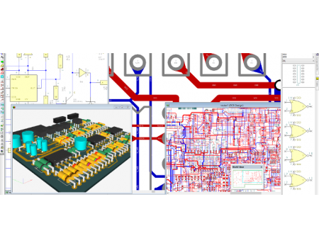
Easy-PC is a complete schematic capture and printed circuit board electronic CAD software solution.
Features
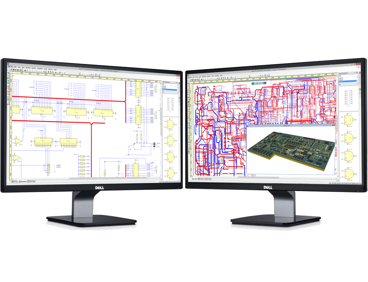
Easy to use
Everything in Easy-PC has been designed with ease of use in mind. In most cases, the main menus are hardly used with shortcut menus being used in all contexts. Try it and see for yourself.
Global Technology Files for fast start-up
Use global technology files to ensure conformity to your company/manufacturing design requirements. Technology files contain predefined design information, styles and rules such as Pad/Text/Track Styles, Layers, Spacing rules and colours to be used within the design.
Library Management Tools
Edit and manage your library items; Schematic Symbols, PCB Footprints, Components and 3D packages in one single management tool. All stages of the process are easy to do and result in correct first time libraries.
Library Creation Wizards
Library creation wizards enable you to create Schematic Symbols, PCB Footprints and Components simply and efficiently. Wizards guide you step-by-step through a sequence of operations resulting in the automatic generation of new library items, simply and efficiently.
Automatic Project Versioning
Manage a new version of your complete Project without the need to manually include and remember files within it. All files can be saved using new names and/or with numbers to denote new versions.
Assembly Variants
Easily create two or more variations of your design without having to create separate design files or have to resort to complicated schemes to create your Bill of Materials (BOM).
3D Preview
Preview your PCB Design in the 3D Viewer enabling you to visualise the design before it ever becomes a physical PCB! You can also print the 3D view to an image for use in documentation.
Instant Cross Probing of designs
Instant bi-drectional cross probing is available between the Schematic and PCB layout designs. All aspects of the design can be probed and highlighted, such as pads, terminals, nets and Components.
Standard Manufacturing Outputs
Easy-PC has all the standard manufacturing outputs you'd expect from a professional product. Outputs are avaiable for Gerber, Excellon, Windows, ODB++, GenCAD, Bill of materials (BOMs), Pick & place reports, Assembly drawings, Bitmaps and WMF, and many more.
Schematic Capture
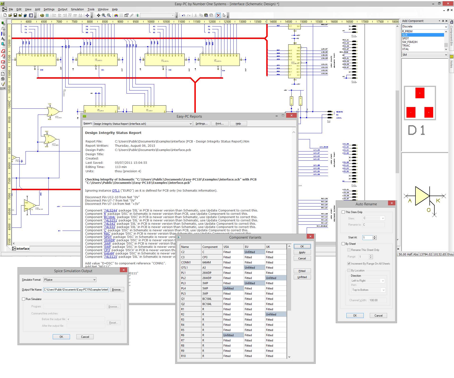 Create clear and concise Schematics
The Easy-PC Schematic editor allows you to create clear and concise schematic drawings. Multi-sheet drawings can be easily combined within a project file, allowing all net and component names to be managed and synchronised.
Design Rules Checking
The Design Rule Check examines your Schematic designs, check for a number of possible errors to help you avoid downstream problems in generating the layout or more often in using the Schematic as documentation for engineers to troubleshoot the finished boards.
Intelligent Busses
Intelligent bus items can be drawn in the design with ease. These busses can be 'closed' containing specific net names, or they can be left 'open' to give you flexibility. Bus nets can be drawn with connective nets or left for full implied (invisible) connectivity.
Schematic Hierarchy
Schematic design sheets in a project can have a hierarchical structure. These can be a combination of both 'Top Down' and 'Bottom Up'.
Colour by net in Schematics
To aid recognition of important nets when designing your Schematic, each net can be given its own colour. These colours can be set up in the Schematic Technology, allowing you to define schematic net colours for all your designs.
Forwards and Backwards Annotation
Updates and modification to Schematics can be passed forward to PCB with name changes in the PCB being back annotated to Schematic design.
Spice Netlist Exports
- Generic
- B2 Spice
- IsSpice
- LT Spice
- Micro Cap
- PSpice
- SiMetrix
- Spice3
- Tina
- TopSpice
Unlimited Pin Schematic Editor
All schematic editors supplied with Easy-PC are unlimited in their symbol pin count.
PCB Layout
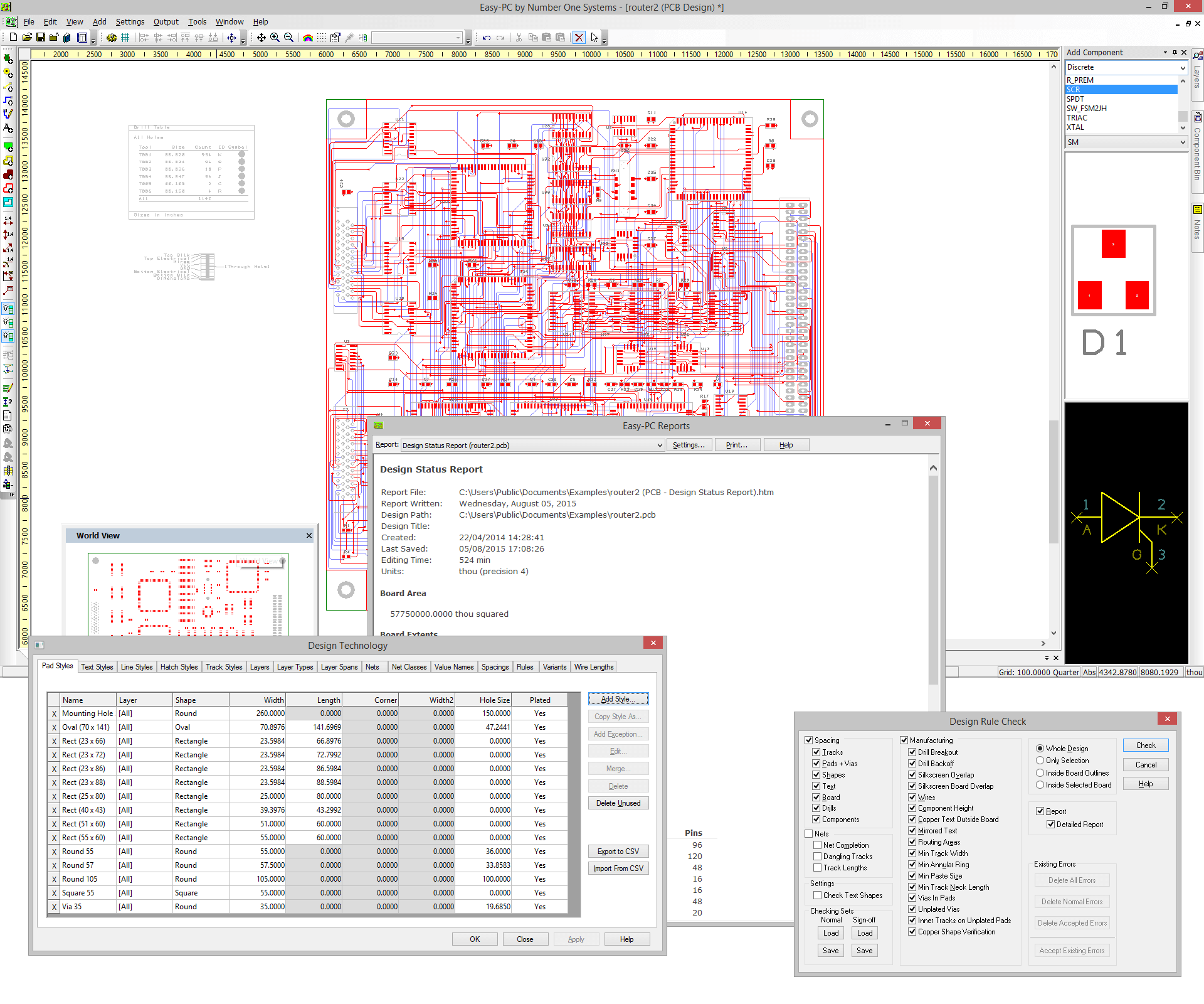 1000, 2000 and Unlimited Pins
Easy-PC can be purchased according to three pin variant options; 1000, 2000 and Unlimited Pin license. These allow you greater flexibility for license purchasing according to the size of your designs.
The pin calculation is based upon physical pins/pads within a design.
Design Reuse
Using the intelligent Apply Layout Pattern feature within Easy-PC, you can define a piece of circuitry or 'Golden Circuit', and apply the layout positions and routing of that defined circuit to a series of grouped parts within the design. This dramatically reduces design time and ensures accuracy of trace lengths.
Online Design Rules Checking
With online DRC (Design Rule Check) switched on, error markers instantly indicate design rule spacing errors and the error location during the design layout process.
Integrity and Connectivity Checking
Detailed report comparing netlist information for the Schematic and PCB, allowing for the investigation of any discrepancies found.
Net Optimisation
The Net Optimisation feature enables unrouted connections to show the shortest possible length on the Net.
Shape Based Copper Pour
Easy-PC provides fast copper pouring with control on thermal relief, isolation gaps, and the number of spokes, plus removal of unwanted copper 'islands'. Flexible, powerful and easy-to-use, add copper of any shape to the design.
Split Powerplanes and View Powerplanes
Easy-PC offers full support for split and partial powerplanes. The view powerplane facility enables you to view the powerplane using the same mechanism as used for generating it at the plotting stage, this ensure accuracy rather than simply looking at a "bitmap" image.
Via Stitching in/around Copper Areas and Tracks
In depth rules allowing you to define the style and positioning of vias in or around Copper Areas and Tracks.
Autoplace
Autoplace is provided as standard with Easy-PC. With an easy-to-use dialog it allows you to place or test place components from your component bin for suitable placement positions within the design.
Manufacturing Outputs
- Gerber X2, RS-274-D and RS-274-X
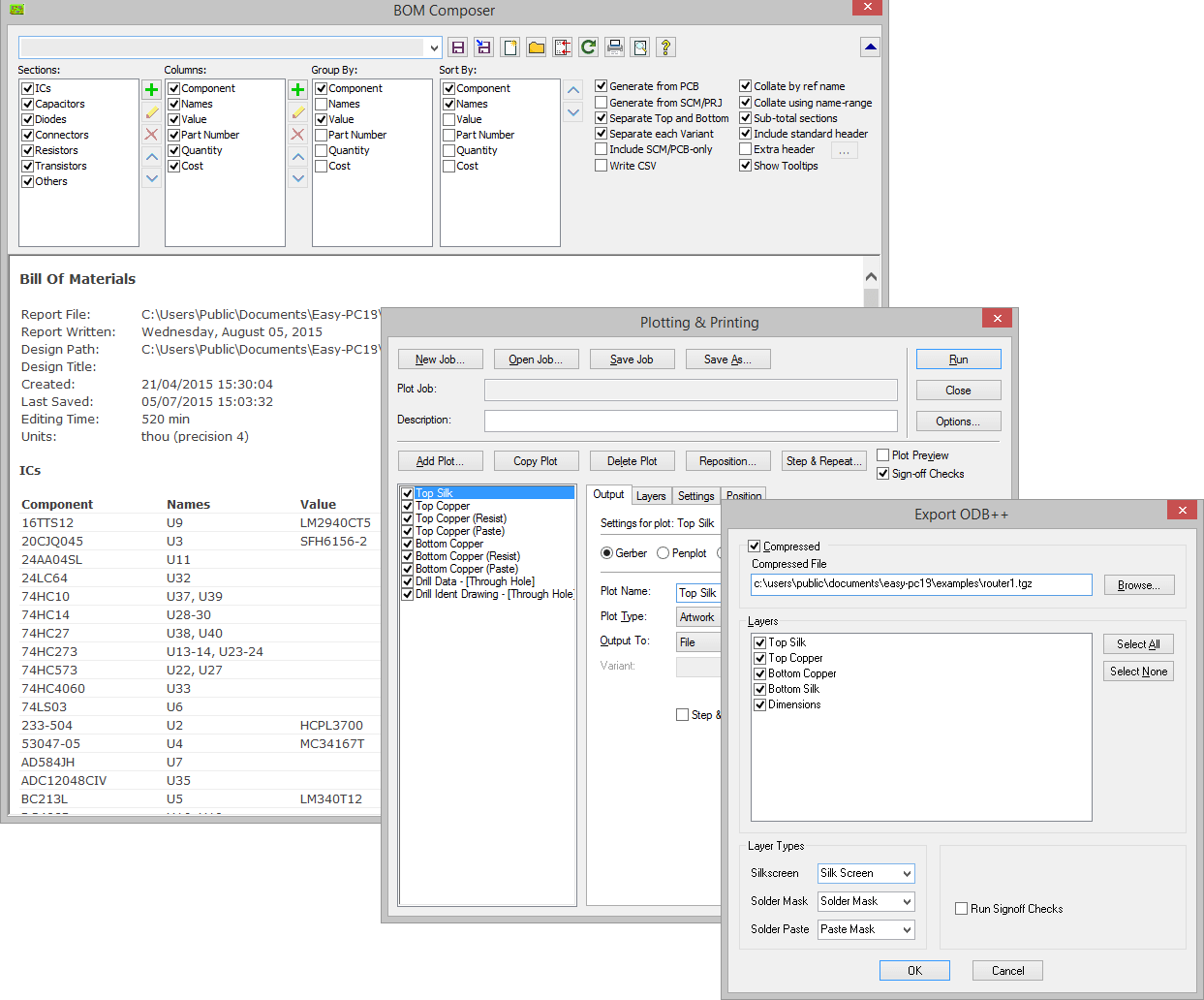
- DXF
- Excellon NC Drill Output
- IDF
- ODB++
- Parts list and BOM (Bill Of Materials) in text, CSV and HTML format
- Pick and Place Assembly Outputs
- User defined Parts/Net List Outputs
- GenCAD
- Output to Bitmap
- HPGL A and B pen plotters
Auto Routers
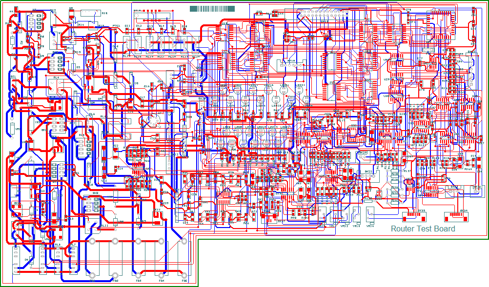 Trace-Router
Trace-Router is our entry-level autorouter and is fully integrated within Easy-PC. It is a modern rip-up and retry autorouter that utilises a numerically stable mathematical topology. This coupled with a highly efficient push-aside routing algorithm makes this router ideal for most types of designs.
All the PCB variants of Easy-PC have TraceRouter bundled in with the product, or it can be added for a small additional cost.
Pro-Router
The Pro-Router delivers fast, high completion rate auto-routing on the most densely packed, multi-layer PCB designs. A high performance router delivering minimal overall track lengths and via counts; Pro-Router provides the ideal routing solution for large or complex designs.
Pro-Router is a new generation of auto-routing software using a multi-pass cost-based conflict reduction algorithm to find a routing solution adapting to the natural flow of the nets. Adaptive routing algorithm is the only proven approach to reach high completion rates on the modern generation of designs.
Click Here to go to the Auto Router Information and ordering page.
Libraries
- Pro Library
- Micro-Controller Library
- Connector Library
- IPC-Surface Mount Library
Click Here to go to the Library Information and ordering page.
Imports
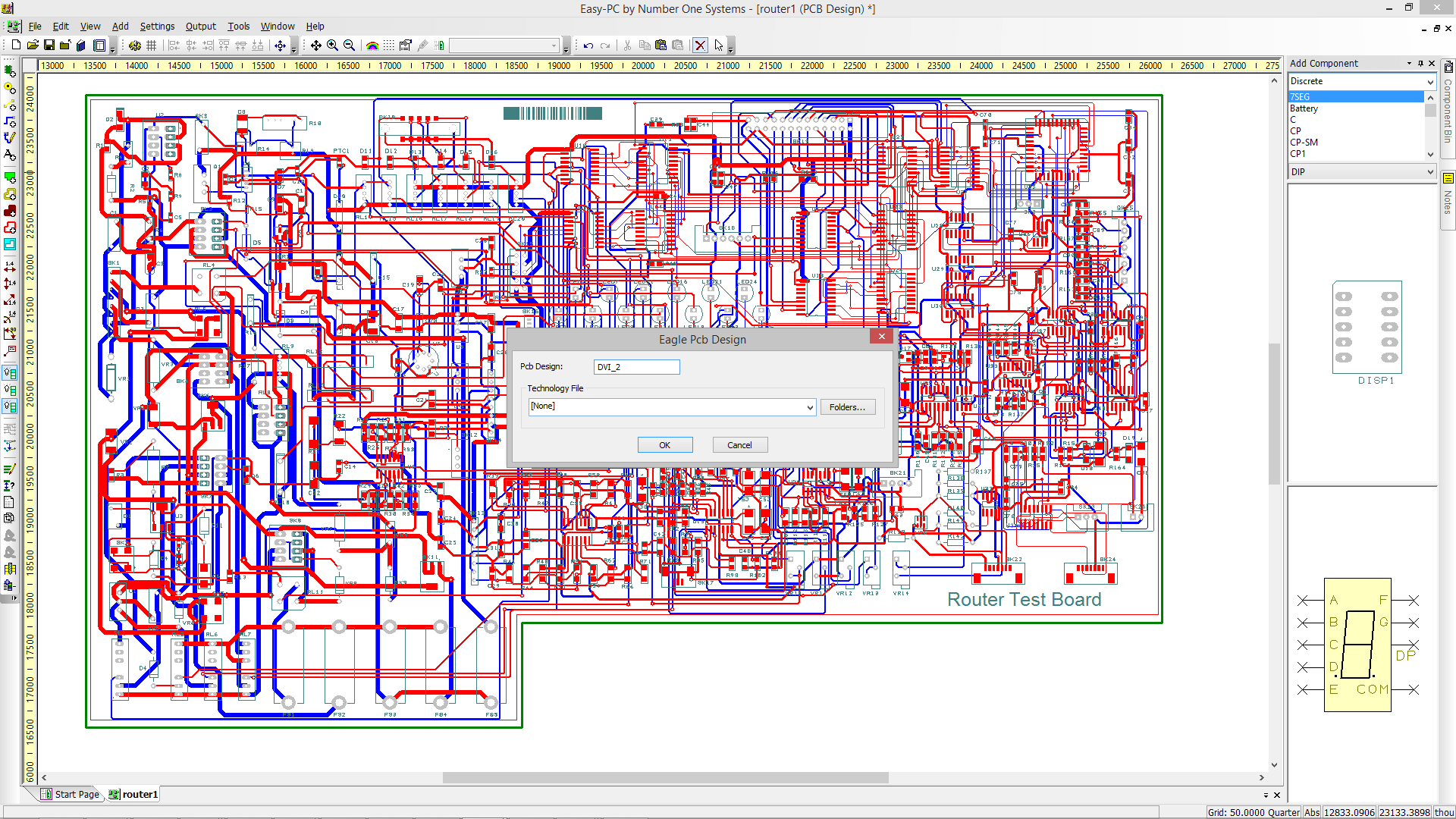 BoardMaker 1 & 2 (Designs and Libraries)
- Bitmap
- DXF
- Eagle (Designs and Libraries)
- Easy-PC Pro, Pro-XM (Designs and Libraries)
- Electronics Workbench Netlist format
- Gerber
- Import CSV Placement Data
- OrCAD Native EDIF Netlist format
- Ultiboard and UltiCAP format (Designs and Libraries)
| Pin Versions | |
| Different Pins | Easy-PC pin variations are only functionally different in the number of pins on the printed circuit board. For example 1000 pins allows only 1000 through holes/pins/pads on the PCB vias are not counted but component pins are. Otherwise the all have the same functionality. |
Related Products
Easy-PC Latest Update
EASY-PC VERSION 29 HIGHLIGHTS Version 29 For Version 29 Highlights and Features Click thi..
$154.00
Easy-PC 1000 Pins
Easy-PC is a complete schematic capture and printed circuit board electronic CAD software solution. ..
$527.00
Easy-PC Unlimited Pins
Easy-PC is a complete schematic capture and printed circuit board electronic CAD software solution. ..
$897.00
Connector Library 3 For Easy-PC
Connector Library version 3.1 The Connector Library provides a large collection of over 14,000 co..
$137.00
Tags: easy-pc, 2000 pins, Schematic and PCB Layout, PCB Design Software

